In this tutorial we build on from the drag estimation and specify an engine and propeller combination in order to determine the variation in thrust with airspeed. Most ships are equipped with twin screws and the propeller turn opposite ways either outward or inward.

Propeller Design Calculation Pdf Lift Force Fluid Mechanics
Thesis BUET Bangladesh 2015.
. Select blade section thickness and camber distribution using for instance tabulated data in books such Abbott von Doenhoff Theory of wing sections 3. The calculation of Marine Propellers based on lifting surface theory. The project was set up with a twin engine and Ive already done power and shaft calculation which formulas were from Dave Gerrs book.
Large vessel often have twin screws. The rotation of the propeller adds momentum to the air tube where momentum is equal to the mass of air function of diameter multiplied by the rearward velocity. Propeller design is important technology for energy saving in ship propulsion.
The calculated propeller sizes are based on standard propeller designs. Hi Im a first year student in boat design and doing calculating for a propulsion system of a 13 meters boat. ISO 484-1 2015 and ISO 484-2 2015 which now supersede the earlier 1981 standards define the requirements for propellers greater than 25 m and between 080 and 25 m respectively.
More than that is a pretty steep pitch. Up to 24 cash back Agitator Design Mech Spreadsheet. In Part 9 we completed a preliminary drag estimation of a new light sport aircraft design.
SHP BHP 097 100 - 0015 number of bearings 100 Displacement in pounds. Large pitch propellers may have a good efficiency in their design point but may run into trouble when the have to operate at axial velocity. If a prop is angled 25º at the circumference it will be oversquare by a factor of 146.
From P E service vs V S curve at 353982 kW obtain V sservice V Sservice. This calculator is free to use as often as you wish. Kaplan Propeller Design Spreadsheet I am looking for a Kaplan propeller series spreadsheet that allows me to adjust speed diameter blade number etc.
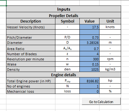
Propeller design calculation Diam kinvisk n pa pv rho_s z r k m a Vs knots T kN RPM D m w c xx G Circulation distribution parameters. Check of risk of cavitation 3. M omentum M assV elocity M o m e n t u m M a s s V e l o c i t y More.
Determination of camber and pitch distribution. Welcome to White Rose eTheses Online - White Rose eTheses. Calculation of marine propellers DNV GL AS SECTION 2 CALCULATION OF HIGH CYCLE STRESSES IN PROPELLER BLADES 1 High cycle stress criterion Dynamic stress amplitudes in the propeller blade shall fulfil the following criterion.
Prediction of the ship speed and propeller rate of rotation in service with the engine 85 of MCR. Calculation of thrust and torque 2. Starting from the site data the turbine speed should be chosen to give a specific speed which fits with the.
You must perform stability calculations after doing your design layout. σA dynamic stress amplitude S safety factor U fatigue strength amplitude. Rahman A Development of a marine propeller design method based on lifting line theory and lifting surface correction factors M.
The flow chart on page 3 outlines the stages in the design procedure. A Bp- diagram or experience might be used. Aircraft Engine and Propeller Sizing AeroToolbox.
UTmean UAmean Cxzbi Goldstein factor from diagram blades UT UA VA n Hz Lift Nm CL Rn Blade section lift coefficient Dimless radius. Select propeller diameter and RPM. A twin screw propeller consist of two propellers arranged side by side at the stern of the ship.
Calculation of thrust and torque 1. Design radial chord length distribution cr 4. MISSION PROPELLER DESIGN AND ANALYSIS 39 51.
For general propeller design work the ISO specifications usually serve as the criteria for assessment. The stresses referred to are principal stresses. 2 blade 30 blade area ratio 3 blade 50 blade area ratio 4 blade 69 blade area ratio.
P D P B η S. Rather than custom-making this you may be able to find it at a boat prop shop. STAGE 3 Prediction of performance in service.
Usually the best overall propellers will have a pitch to diameter ratio in the order of 1. Now to complicate matters static thrust is proportional to the exit velocity squared so in this example the 2-bladed prop would produce 142 196x as much thrust as the 1-bladed prop the 3-bladed prop would produce 162 256x as much thrust and the 4-bladed prop would produce 172 289x as much thrust. P E P D η D.
The propeller diameter has a big impact on performance. The calculations for each step have been put into the spreadsheet. Journal of Ship Research 5 2 1961 Google Scholar.
A Bp-δ diagram or experience might be used. Welcome to Part 10 the final installment in the Fundamentals of Aircraft Design series. Np Graph and User Guide will be provided along with spreadsheet.
Pi x tan 25º See Rixters note on washout. The results are only as acurate as the data you enter. Empirical formula Chord length.
Normally the Crouchs propeller method can be used for calculating a single prop. 421 Initial Propeller Design 23 422 Initial Propeller Analysis 28 43. A prop whose pitch equals its diameter is said to be square.
Anchor Propeller Pitched Blade Turbine Chemineer HE-3 Hydrofoil Sawtooth Curved Blade Turbine Straight Blade Turbine Disk Turbine. η D assumed 07. The calculations and results are based on imperical data and formulas.
Cruise q Cruise WS Cruise LD Cruise Prop efficiency Cruise Advance Ratio J Wfuel total Wfuel usable Wfuel cruise log term Range Simplified Aircraft Design Spreadsheet for Homebuilders Takeoff to 50 ft Wing Flight Controls Horizontal Tail Instruments Vertical Tail. Aerofoil Selection 30 44. Calculation of thrust and torque 1.
I am currenty working on a KA4-70 however the geometry is not correct. Select blade section thickness and camber. Select propeller diameter and RPM.
20 Turbine Design Spreadsheet The design procedure follows a series of logical steps. W in service 11 w in trial 03344. The propeller design calculation consists of three steps.
Aerofoil Analysis 32 441 Choice of Aerofoil Analysis Code 32 442 Radial Distribution of Aerofoil Sections 34 443 Prediction of Aerofoil Characteristics 34 5. In this case the blades tend to stall. In certain cases such as naval propellers the purchasers of the propeller may.
Step 4 Propeller Selection The Uav Chronicles

Propeller Blade Thickness Calculation Spreadsheet Www Thenavalarch Com Youtube

Propeller Design Calculation Pdf Lift Force Fluid Mechanics
Wageningen B Series Propeller Designer Thenavalarch
.PNG)
Propeller Static Dynamic Thrust Calculation Flite Test
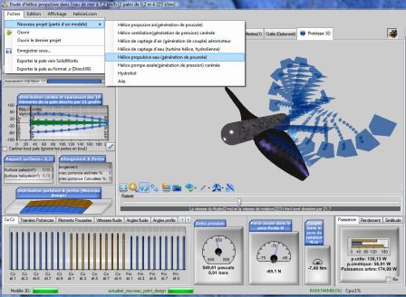
Software Propellers Design Screw Calculator Boats Aerial Wings Hydrofoils

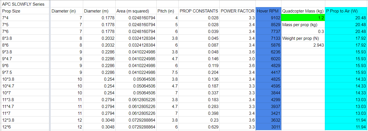
Propeller And Motor Selection Quadcopterproject

Propeller Design Calculation Results Download Table
0 comments
Post a Comment